 3D Printer FYI
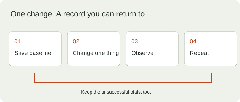
Calibration becomes much less mysterious when you can return to yesterday’s settings. Before changing anything, save the project, export the profile, photograph the result and write down the material and nozzle. “The default profile” is not a revision identifier.
The goal is a repeatable result for a stated job. A beautiful calibration object is useful only if it tells you something about the parts you intend to make.
Establish the baseline
Record the printer and firmware, nozzle diameter, material brand and formulation, spool condition, build surface, slicer version, profile revision and model revision. Follow the machine’s maintenance and calibration procedure before tuning around a mechanical problem.
Download the blank calibration record. It contains column headings, not made-up observations. Keep photographs beside the file using the same experiment ID.
Start where the part starts
Inspect the first layer before using the rest of a print to judge a setting. Prusa’s manual first-layer guidance describes visibly different outcomes when nozzle distance is too large or too small. Its procedure is model-specific; use your printer’s corresponding procedure rather than copying a Z value from a different machine. First-layer calibration
If the failure is unclear, choose a symptom in the troubleshooter. Record what each check found. Completing a check does not prove its possible cause was responsible.
Change one thing you can explain
Write the hypothesis before the adjustment: “This change should reduce this visible gap under these conditions.” Choose an observation that could show you were wrong.
Extrusion multiplier is one possible adjustment, not a universal repair. Prusa documents calibration approaches based on a printed specimen and its appearance or measurements. Use a documented method with its assumptions, and retain the original value. Extrusion-multiplier calibration
For an illustrative experiment, keep the same model, spool and orientation while comparing your existing profile with one altered setting. Label both outputs. Do not change flow, temperature and speed together and then attribute the result to one of them.
Use the actual mating part
For a fit problem, print a small set of labeled coupons using the process planned for the final part. Record CAD diameter, measured hole diameter where available, mating-part diameter, measurement method and observed fit in the Fit and Fastener Workbench.
An illustrative 5.20 mm measured hole around a 5.00 mm measured pin has 0.20 mm diametral clearance. For ideal concentric circles that is 0.10 mm per side. Those arithmetic results do not establish what your next printed hole will measure.
Prusa explicitly notes that a universal tolerance does not exist across geometries and processes. Keep your conclusion scoped to the tested configuration. Design guidance
Inspect what the slicer requested
When a preview seems implausible, inspect the generated file in the G-code Microscope. Follow a segment back to its command and check positioning modes and resets. Read the interpretation warnings before trusting totals.
The microscope supports a documented linear subset. It does not reproduce every firmware feature or calculate an exact completion time. A disagreement between its view and the slicer is a question to investigate, not automatic proof that either file is defective.
Repeat before adopting
Print the candidate setting again under the same recorded conditions. If the apparent improvement disappears, retain both outcomes. A useful record includes unsuccessful experiments.
| Result | Next action |
|---|---|
| Repeatable improvement in the target feature | Save a new profile revision with the reason |
| Improvement with an unacceptable side effect | Keep the baseline and design another test |
| Inconsistent outcome | Investigate uncontrolled conditions before choosing a winner |
| No meaningful change | Restore the baseline and test another explanation |
This table is an experiment-planning aid, not a diagnostic decision tree. Finish with a small version of the real job. Export the fit study or calibration record and keep the known-good project. The best setting is one you can explain, reproduce and undo.
Related: Your G-code has a memory and The hole you drew is not the hole you printed.
Sources
- First-layer calibration — Prusa — reviewed 2026-09-15.
- Extrusion multiplier — Prusa — reviewed 2026-09-15.
- Designing for printing — Prusa — reviewed 2026-09-15.